
Control Circuit Troubleshooting: Reading Schematics Like a Pro
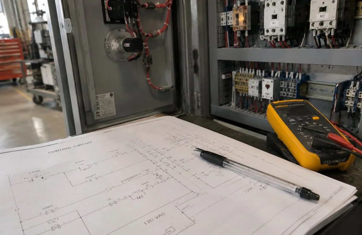
Control circuit troubleshooting starts with the schematic. A technician who can trace the intended path of control voltage, identify each permissive, and compare the drawing with the actual panel can isolate faults faster and avoid replacing working components. For maintenance leaders, that skill supports safer work, less downtime, better root-cause findings, and a clearer development path from entry-level technician to senior technician.
A control schematic does not show every wire exactly as it is routed in the enclosure. It shows how the circuit is meant to function. Your maintenance team must learn to read that functional sequence before testing electrical equipment in the field.
Give your technicians a common troubleshooting method with electrical troubleshooting training for your team.
What Is a Control Circuit?
A control circuit is the part of an electrical system that commands, monitors, or protects a load. It may energize a contactor coil to start a motor, stop a conveyor when a guard opens, or prevent a pump from restarting after an overload condition.
The control circuit is separate from the power circuit, although the two work together. The power circuit carries the current used by the motor or other load. The control circuit uses switches, relays, overload contacts, sensors, timers, and logic devices to decide whether the power device should operate.
For example, a motor starter control circuit may include a control transformer, fuse, emergency-stop contact, stop pushbutton, overload relay contact, start pushbutton, auxiliary seal-in contact, and contactor coil. If one required series device remains open, the contactor coil cannot energize, and the motor will not start.
Read the Schematic Before You Test
A schematic is a functional map. Most industrial control diagrams show contacts and devices in their normal, unactuated state unless the drawing notes otherwise. “Normally open” and “normally closed” describe a contact’s condition when its operating device is not actuated, not necessarily its condition while the machine is running.
Start by locating these items:
| Schematic Item | What It Tells You | Why It Matters During Troubleshooting |
|---|---|---|
| Control power source | Where control voltage begins and returns | Confirms the expected voltage and test reference |
| Wire numbers and terminal numbers | The physical points connected by a conductor | Helps your technician move from the print to the panel |
| Device designation | The relay, contactor, switch, or overload being referenced | Links a coil to its associated contacts elsewhere in the drawing |
| Cross-references | Where a contact, coil, or related circuit continues | Prevents missed logic on another page or rung |
| Contact state | Whether a contact is shown open or closed in its normal state | Helps identify which conditions must change for the circuit to operate |
| Load or output | The contactor coil, solenoid, relay coil, or PLC output being controlled | Defines the final device that must receive the correct signal |
Different OEMs may use different drawing conventions. The IEC 60617 database provides standardized graphical symbols for diagrams, while many North American prints use familiar NEMA- and ANSI-style conventions. Your team should be able to recognize the symbols used in the equipment installed at your facility rather than assume every drawing uses the same format.
For a structured foundation in symbols, prints, and circuit tracing, see ITC Learning’s electrical print reading course.
Safety Comes Before Electrical Troubleshooting
Troubleshooting electrical circuits can require both de-energized checks and energized measurements. The correct method depends on the task, equipment, hazard assessment, company procedure, and qualifications of the person performing the work.
OSHA requires employers to control hazardous energy during covered servicing and maintenance work. It also makes an important distinction: pushbuttons, selector switches, and other control circuit devices are not energy-isolating devices. A technician cannot treat pressing Stop or opening an interlock as lockout/tagout. Review OSHA’s lockout/tagout standard, 29 CFR 1910.147, alongside your facility’s energy-control procedures.
For exposed electrical parts, OSHA generally requires de-energization before work unless de-energizing creates a greater hazard or is infeasible because the task requires energized testing. In those cases, only qualified personnel using appropriate work practices, PPE, insulated tools, and test equipment should perform the work. See OSHA 29 CFR 1910.333. Many facilities also use NFPA 70E electrical safety guidance within their electrical safety programs.
Common Control-Circuit Fault Modes
Most control-circuit faults fall into a small number of patterns. Teaching technicians to recognize these patterns reduces guesswork and makes troubleshooting more consistent.
| Fault Mode | What Happens | Common Causes |
|---|---|---|
| Open circuit | Current cannot complete its intended path | Tripped overload relay, open stop circuit, broken wire, failed limit switch, loose terminal |
| Short circuit | An unintended low-resistance path causes excess current | Damaged insulation, pinched conductors, moisture, damaged components |
| Low control voltage | A coil or relay receives insufficient voltage to operate reliably | Undersized transformer, excessive voltage drop, loose connections, overloaded control transformer |
| Intermittent circuit | The machine fails only under certain conditions | Vibration, heat, corrosion, mechanical damage, loose connections |
| Failed coil or contact | The device does not change state as expected | Open winding, damaged relay coils, pitted contacts, mechanical binding |
| Incorrect feedback or permissive | The control system does not receive the state it expects | Misadjusted sensor, incorrect wiring, failed auxiliary contact, PLC input issue |
A visual inspection is often the first step, but it is not the final diagnosis. Look for heat discoloration, damaged insulation, loose connections, contaminated terminals, or mechanical damage. Then use the schematic and safe measurements to determine whether the observed condition is the root cause or only a symptom.
A Systematic Control Circuit Troubleshooting Process
A good process follows the logic of the drawing. It does not start with replacing the contactor, relay, fuse, or overload relay because it appears related to the failure.
1. Define the symptom and expected operation
Ask what the equipment should do and exactly what it does instead. Does the motor fail to start? Does it start and immediately stop? Does the contactor coil chatter? Does the motor continue running after Stop is pressed?
Record when the electrical issue occurs, whether it is intermittent, recent equipment changes, alarms, and conditions such as load, temperature, or vibration. This narrows the part of the control system your team needs to examine.
2. Find the output that is not behaving correctly
Locate the contactor coil, control relay, solenoid, or PLC output associated with the symptom. Then identify every device that must permit that output to operate.
For a simple motor starter, the coil may require a closed emergency-stop contact, closed stop contact, reset overload relay, closed guard switch, and momentary start command. A schematic shows the sequence clearly even when those devices are physically spread across the machine.
3. Trace the intended control-voltage path
Follow the circuit from the source to the output and return. Read each device in order and ask: “What condition must this device satisfy for voltage to continue?”
A typical start circuit may follow this path:
-
Control transformer secondary
-
Control fuse
-
Emergency-stop contact
-
Stop pushbutton contact
-
Overload relay contact
-
Start pushbutton and seal-in contact
-
Contactor coil
-
Control-circuit return
The first device that does not pass the expected signal is where the investigation should focus.
4. Use de-energized and energized checks appropriately
With equipment de-energized and verified safe under your facility procedure, technicians can inspect connections and test continuity or resistance where appropriate. This can identify an open contact, broken conductor, or failed coil.
When a measurement must be taken with the circuit energized, the work must follow your organization’s electrical safety program. Do not bypass an interlock, jumper a safety device, or defeat protective logic simply to make a machine run. The goal is to determine why the circuit does not meet its intended operating conditions.
5. Confirm the root cause and validate the repair
A repaired wire, reset overload, or replaced contact block is not proof that the problem is solved. Test the full sequence under normal operating conditions when it is safe to do so. Confirm that the control device energizes, related feedback changes state, the electrical load operates correctly, and protective devices remain functional.
Document the fault, test points, readings, repair, and follow-up action. That record helps your maintenance team catch repeat problems and supports proactive maintenance planning.
For a broader framework that connects electrical faults to root-cause troubleshooting, use this electrical troubleshooting guide.
Example: Control Circuit Troubleshooting for a Conveyor Motor
Assume an operator presses Start on a conveyor, but the contactor does not pull in. The power circuit may be healthy, but the control circuit is open somewhere in the start sequence.
The technician first reviews the schematic and finds that the contactor coil requires the emergency stop, stop pushbutton, overload relay contact, and guard switch to be closed. The technician then follows the approved troubleshooting process to check the circuit in sequence.
If the overload relay contact is open, resetting it may restore the control circuit temporarily. But the team still needs to determine why it tripped. The motor may have been overloaded, the conveyor may be binding, a phase problem may exist in the power circuit, or the overload may be incorrectly set. Replacing or resetting a component without checking the reason for operation can lead to repeat downtime.
Control Circuits, Ladder Logic, and PLCs
Modern equipment may combine hardwired control circuits with PLC logic. A physical pushbutton, sensor, overload contact, or safety relay can provide an input to the PLC, while the PLC determines whether to energize an output.
The troubleshooting principle stays the same: compare the expected sequence with the actual state of each device. Start at the field device, verify the input, review the logic condition, confirm the output, and then check the final control device.
When the issue involves inputs, outputs, alarms, or logic status in a programmable controller, use this PLC troubleshooting step-by-step guide.
Schematic-Reading Checklist for Your Maintenance Team
Use this checklist as a printable job aid or downloadable training resource for control circuit troubleshooting:
-
Confirm the machine symptom and the expected normal operation.
-
Review the current revision of the schematic before opening the panel.
-
Identify the control-voltage source, fuse or circuit protection, output device, and return path.
-
Read contacts in their normal, unactuated state unless the drawing notes otherwise.
-
Match wire numbers, terminal numbers, and device designations from the drawing to the equipment.
-
Identify all required permissives, interlocks, overload contacts, and safety devices.
-
Follow your energy-control and electrical safety procedures before touching conductors or components.
-
Use only approved test methods and qualified personnel for energized testing.
-
Correct the verified root cause, not only the visible symptom.
-
Test the complete operating sequence and document the result.
Give supervisors, technicians, and planners a shared troubleshooting language with electrical troubleshooting training for your team.
Building Schematic-Reading Capability Across the Workforce
Control circuit troubleshooting is a workforce capability, not just an individual skill. When technicians use different methods or cannot connect a schematic to actual equipment, diagnosis takes longer and repeat failures become more likely.
Your organization can build consistency through training that combines electrical fundamentals, print reading, meter use, safe work practices, ladder logic, and supervised application on facility equipment. Establish a common troubleshooting form, require clear fault documentation, and use recurring failures as training examples. This creates a more reliable maintenance process while helping technicians advance into higher-responsibility roles.
For Technicians and Apprentices
If you are building your electrical troubleshooting skills, practice tracing simple start-stop circuits before moving to more complex control systems. Learn to identify a coil, normally open contact, normally closed contact, overload relay, control transformer, and auxiliary contact on both the schematic and the equipment.
The goal is not to memorize symbols alone. It is to explain what must happen for the circuit to operate, identify where that sequence stops, and verify the reason with safe, approved methods.
Build Control Circuit Troubleshooting Skills
Consistent schematic reading and troubleshooting help maintenance teams diagnose faults faster and develop stronger technician skills. ITC Learning provides structured electrical training to support that capability.
Build a more capable electrical maintenance workforce with electrical troubleshooting training for your team.
Why Organizations Choose ITC Learning
-
50+ years developing skilled-trades training
-
1M+ learners trained
-
175+ courses · 450+ lessons
-
SCORM-compliant · Deliverable via ITC LMS or your existing platform
-
Available in English and Spanish
-
Supports manufacturers, industrial employers, educational institutions, workforce development programs, apprenticeships, and CTE partnerships