
Multimeter Troubleshooting: 12 Techniques Every Technician Should Know
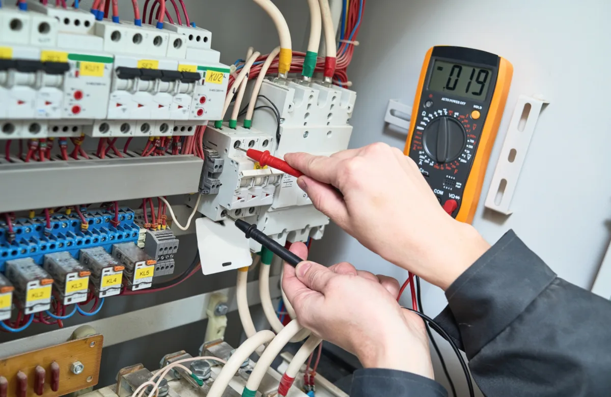
Multimeter troubleshooting uses voltage, current, resistance, continuity, and component measurements to locate electrical faults systematically. Instead of replacing parts based on symptoms, technicians compare readings with schematics, equipment specifications, and known operating conditions. This process can reveal open circuits, excessive resistance, failed components, unstable power supplies, and other problems that affect equipment reliability.
For maintenance leaders, multimeter competency supports faster fault isolation and more consistent troubleshooting across shifts. It also gives supervisors an observable skill that can be assessed, practiced, and reinforced through electrical troubleshooting training for your team.
Safety note: Electrical testing should only be performed by qualified personnel following the facility’s electrical safety program, lockout/tagout procedures, equipment documentation, and applicable regulations. Live measurements require additional precautions and should be avoided when the diagnostic objective can be achieved with the equipment de-energized.
Start With a Repeatable Troubleshooting Framework
A digital multimeter provides data, but the reading alone does not identify the fault. Technicians need a disciplined process for deciding what to measure and interpreting the result.
A practical workflow includes:
-
Confirm the reported problem.
-
Review the schematic and sequence of operation.
-
Identify the expected electrical state at each test point.
-
Inspect the equipment for visible or obvious defects.
-
Select the correct meter, leads, function, jacks, and range.
-
Begin at a known reference point.
-
Divide the circuit into sections and test one section at a time.
-
Compare each measurement with the expected value.
-
Locate and correct the fault.
-
Test the equipment through a complete operating cycle.
The first thing a technician should ask is not, “What component should I replace?” It is, “What should be happening at this point in the circuit?” The broader electrical troubleshooting guide explains how this measurement process fits into a complete fault-diagnosis framework.
Multimeter Safety Before Testing Begins
Before attempting any test, inspect the meter body, display, selector switch, probe tips, leads, and input jacks. Remove damaged equipment from service. Under OSHA 29 CFR 1910.334, test instruments and associated test leads, cables, probes, and connectors must be visually inspected for external defects and damage before use, and electrical testing must be performed by qualified persons.
Technicians should also:
-
Select a meter and leads with an appropriate measurement-category rating for the environment.
-
Confirm that the meter’s voltage and current limits exceed the anticipated parameters.
-
Verify that the black lead is in the COM jack and the red lead is in the correct voltage, resistance, or current jack.
-
Use required personal protective equipment and safe probe-handling practices.
-
De-energize and lock out equipment before continuity, resistance, diode, or capacitance testing.
-
Discharge capacitors according to the manufacturer’s instructions before touching or testing them.
-
Follow an approved absence-of-voltage verification procedure when zero volts must be confirmed.
IEC 61010-2-033:2023 specifies safety requirements for handheld multimeters capable of measuring mains voltage. The meter’s CAT rating describes its ability to withstand transient energy in a particular electrical environment; it is not simply a maximum-voltage label.
OSHA generally requires exposed live parts to be de-energized before employees work on or near them unless de-energizing introduces greater hazards or is infeasible because of equipment design or operational limitations. Those requirements are detailed in 29 CFR 1910.333.
12 Multimeter Troubleshooting Techniques
The techniques below cover practical ways technicians can use a multimeter to test circuits, verify conditions, and narrow down electrical faults systematically.
1. Check the Multimeter Function, Range, and Leads
Before every measurement, double-check the selector position and input jacks. A dead battery, incorrect function, damaged lead, or other meter issue can produce unreliable readings or prevent the instrument from operating correctly. Use the appropriate input jack for the selected function according to the meter manufacturer’s instructions.
For manual-ranging meters, choose a range above the expected value and adjust downward for better resolution. Auto-ranging simplifies range selection, but the technician must still select the correct function, such as AC voltage, DC voltage, ohms, or amps.
Incorrect settings can produce a misleading reading, blow an internal fuse, damage the meter, or expose the technician to an electrical hazard.
2. Verify the Meter Before Trusting Zero Volts
A zero-volt reading can mean the circuit is de-energized, but it can also result from an incorrect setting, broken lead, poor probe contact, or a failed meter.
When verifying the absence of voltage, follow the facility’s approved procedure. This commonly includes testing the instrument against a known voltage source before and after checking the circuit. A successful check confirms that the meter and leads were functioning when the zero-volts measurement was taken.
A non-contact voltage detector may support an initial check, but it does not replace an approved contact test for verifying an electrically safe work condition. NFPA 70E addresses electrically safe work practices, including establishing an electrically safe work condition.
3. Measure AC Voltage Across the Correct Points
AC voltage measurements help technicians determine whether power reaches disconnects, fuses, contactors, transformers, motors, and other loads.
Measure between the test points identified in the schematic and compare the result with the rated or expected voltage. In a three-phase system, this may require comparing each phase-to-phase measurement. An abnormal reading on one pair can point toward a blown fuse, open conductor, poor connection, or upstream supply problem.
Do not assume that measuring from one conductor to ground provides all the information needed. The correct reference points depend on the circuit design.
4. Measure DC Voltage With the Correct Polarity and Reference
DC voltage is common in batteries, power supplies, control circuits, sensors, and programmable controller systems. Set the meter to DC voltage, place the black probe on the specified common or negative reference, and place the red probe on the test point.
A negative reading often means the probes are reversed, but technicians should also confirm that they selected the correct reference. For example, a low-voltage control signal may appear incorrect when measured against chassis ground instead of the circuit’s designated DC common.
5. Use Voltage-Drop Testing to Find Resistance Under Load
A voltage-drop test measures the voltage consumed across a conductor, contact, switch, connection, or other part of an energized circuit while current is flowing.
Place the probes across the suspected section. A sound closed connection should have little voltage across it, although the acceptable value depends on the circuit and manufacturer’s specifications. A larger-than-expected voltage drop indicates that resistance within the section is consuming part of the available voltage.
This technique is especially useful for locating:
-
Pitted contactor contacts
-
Loose terminals
-
Corroded connectors
-
Damaged conductors
-
Poor ground connections
Resistance measurements made with power off may miss these faults because the weak connection can behave differently under load.
6. Compare Voltage at Each Stage of the Circuit
When a load does not operate, trace voltage through the circuit in a logical order. Start at a known source, then measure before and after each protective device, control, connection, and switching component.
If rated voltage appears before a fuse but zero volts appears after it, the open point has been narrowed considerably.
7. Test Continuity on De-Energized Circuits
Continuity testing determines whether a low-resistance path exists between two points. It is useful for checking wires, closed switches, fuse elements, and contacts after the circuit has been de-energized and stored energy has been controlled.
Before testing:
-
Confirm that power is off.
-
Isolate the circuit or component when required.
-
Touch the probe tips together to check the meter and leads.
-
Place the probes across the test points.
-
Read the displayed resistance as well as listening for the tone.
A beep does not always prove that a connection is good. Continuity thresholds vary among meters, and a resistive connection may still activate the tone.
8. Measure Resistance With the Component Isolated
To measure resistance, remove power and isolate the component from parallel circuit paths when practical. Place the probes across the component and compare the reading with the schematic, nameplate data, or manufacturer specifications.
A reading of OL commonly indicates an open circuit or a value beyond the selected range. A reading near zero ohms may indicate a short, but it may also be normal for a low-resistance winding or conductor. Lead resistance, temperature, and parallel paths can all affect measurements.
Never use the ohmmeter function on an energized circuit. External voltage can produce false results and damage the meter.
9. Measure Current Without Shorting the Circuit
Current measurements require the meter to become part of the circuit. The technician must open the circuit and connect the meter in series, using the correct current jack and range. Placing a meter configured for amps directly across a voltage source creates a low-resistance path and can blow the meter fuse or cause serious damage.
Where appropriate, a properly rated clamp meter or current-clamp accessory can measure current without opening the conductor. This can be a safer and more practical option for industrial troubleshooting.
After the test, move the red lead back to the voltage and resistance jack. This small habit helps prevent the next voltage measurement from becoming an accidental short circuit.
10. Use Diode Mode to Check Semiconductor Junctions
Diode mode applies a small test current and displays the forward-voltage drop across a semiconductor junction. With the component isolated, measure it in both directions.
A typical functional diode shows a forward-voltage reading in one direction and an open indication in the other, but expected values depend on the diode type. Near-zero readings in both directions may indicate a shorted diode, while open readings in both directions may indicate an open device.
The component data sheet should remain the final reference. A diode inside a connected circuit can produce confusing readings because current may travel through other components.
11. Check Capacitance and Account for Stored Energy
A capacitance test can help identify capacitors that are open, shorted, or significantly outside their rated value. De-energize the equipment, follow the manufacturer’s discharge procedure, confirm the absence of voltage, and isolate the capacitor when required.
Compare the measurement with the component’s rated value and tolerance to determine whether the capacitor may be contributing to the fault.
Capacitance alone does not reveal every failure. A capacitor may measure near its rated value yet perform poorly under operating voltage or temperature. Bulging, leakage, overheating, or repeated fuse failures require further evaluation.
12. Capture Intermittent Faults With MIN/MAX Recording
Loose wires, failing power supplies, worn contacts, vibration, and temperature changes can produce faults that disappear before a technician can observe them. If the meter supports MIN/MAX recording, connect it safely at the suspected test point and monitor the equipment through its operating cycle.
For example, a 24-volt control circuit may appear normal when idle but experience a brief low-voltage condition when several loads energize. The recorded minimum reading can reveal the event.
This method is useful only when the meter’s sampling response can capture the disturbance. Faster or more complex signals may require an oscilloscope, power-quality analyzer, or other specialized tester.
Turn Meter Readings Into Reliable Fault Diagnoses
A strong technician does not treat one measurement as final proof. Each result should be checked against four points:
| Diagnostic Question | Why it Matters |
|---|---|
| What should the reading be? | Establishes a valid baseline from the schematic or specifications |
| Were the correct points tested? | Prevents errors caused by the wrong ground or reference |
| Was the circuit in the required state? | Confirms whether the load, control, or process condition was present |
| Does another test support the finding? | Reduces false diagnoses and unnecessary replacement |
High input impedance is helpful because a digital multimeter places little load on many circuits. However, it can also display capacitively coupled or “ghost” voltage on an open conductor near energized wiring. If a suspicious voltage disappears in an approved low-impedance measurement mode, capacitive coupling may be the cause. The meter manufacturer’s instructions and facility procedures should govern how this check is performed.
A structured process also gives maintenance leaders a consistent basis for observation, coaching, and skills assessment. Teams can practice these methods through scenarios involving blown fuses, open wires, low voltage, excessive voltage drop, failed components, and intermittent faults.
ITC Learning’s electrical troubleshooting fundamentals course provides foundational instruction that organizations can incorporate into broader technician-development plans.
Building Multimeter Competency Across a Maintenance Team
Reading a meter is only one part of troubleshooting competency. Technicians must also understand electrical theory, schematics, equipment operation, test-point selection, electrical safety, and the limits of the tool.
Maintenance managers can strengthen consistency with a training process that includes:
-
A written safety and meter-inspection checklist
-
Instructor demonstrations using realistic industrial circuits
-
Guided voltage, resistance, continuity, and current exercises
-
Fault-insertion labs with documented expected readings
-
Performance-based assessments
-
Refresher training for infrequently used skills
-
Clear qualification requirements for energized testing
Standardized exercises make it easier to identify whether a technician needs help with meter setup, circuit analysis, measurement technique, or interpretation. The electrical skills training library can support structured learning paths across foundational and troubleshooting topics.
Organizations ready to develop these capabilities can explore electrical troubleshooting training for your team.
What Individual Technicians Should Practice
Individual technicians should begin with de-energized training circuits and low-voltage equipment under qualified supervision. Practice selecting the correct function and jacks, predicting the expected reading, and explaining what each result means before moving to more complex systems.
Keep notes from each exercise. Recording the test point, circuit condition, expected value, actual measurement, and diagnosis builds a repeatable thought process. The goal is not simply to operate a multimeter effectively. It is to understand how each measurement supports or rejects a possible fault.
Develop a More Consistent Troubleshooting Process
Multimeter troubleshooting is most effective when technicians follow a safe, repeatable process. Correct setup, logical test-point selection, comparison with expected values, and confirmation through a second measurement help turn raw readings into defensible diagnoses.
Plant and maintenance leaders can use these 12 techniques as the basis for lab exercises, performance assessments, and structured learning paths. To strengthen fault-diagnosis capability across your workforce, explore electrical troubleshooting training for your team.
Why Organizations Choose ITC Learning
-
50+ years developing skilled-trades training
-
1M+ learners trained across technical and industrial skills
-
175+ courses and 450+ lessons covering electrical, mechanical, and other skilled-trades topics
-
SCORM-compliant training that can be delivered through the ITC Learning LMS or an existing learning management system
-
Training available in English and Spanish
-
Training that supports manufacturers, industrial employers, educational institutions, workforce development programs, apprenticeships, and CTE partnerships