
PLC Troubleshooting: A Step-by-Step Guide for Maintenance Teams
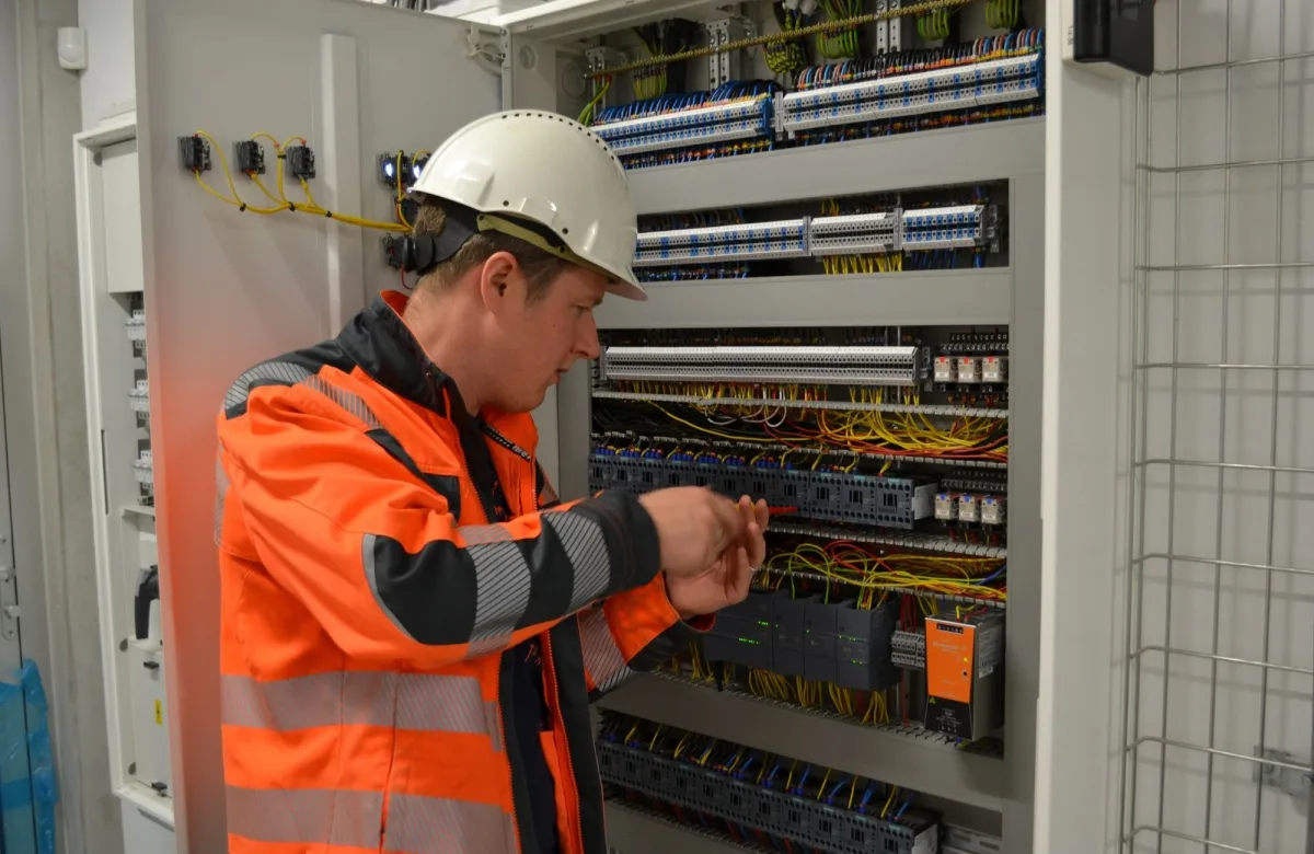
PLC troubleshooting is the systematic process of identifying the cause of a control-system fault by checking power, field devices, I/O modules, program logic, communications, and hardware. Following a structured troubleshooting process helps maintenance teams consistently isolate faults, reduce downtime, and avoid unnecessary component replacements.
This guide explains a structured seven-step PLC troubleshooting process for plant managers, maintenance managers, and technicians responsible for PLC-controlled equipment. It also covers common fault categories, diagnostic tools, safety considerations, and practical troubleshooting techniques. If inconsistent troubleshooting is prolonging repair times across your facility, consider offering electrical troubleshooting training for your team.
What Is PLC Troubleshooting?
PLC troubleshooting involves more than diagnosing the programmable logic controller because the PLC is only one part of an industrial control system. A machine can stop because of a failed sensor, missing permissive, safety interlock, wiring fault, communication problem, failed output device, or process condition even when the controller is operating normally. Effective troubleshooting identifies where the fault originates before repairs begin.
Instead of assuming the PLC has failed, maintenance teams evaluate the entire control system. They verify power, field devices, I/O modules, program logic, communications, and hardware to determine the actual source of the fault. Following a consistent troubleshooting process also helps organizations reduce unnecessary component replacement, improve repair consistency, and make troubleshooting practices easier to standardize across maintenance teams.
These fault-isolation principles also form part of a broader electrical troubleshooting guide that maintenance teams can apply across industrial equipment.
Make the Equipment Safe Before Troubleshooting a PLC
Before troubleshooting a PLC-controlled machine, identify all hazardous energy sources and determine which energy-control and electrical safe-work procedures apply. Deenergize and apply lockout/tagout when required by the task and your facility’s energy-control program. If energized diagnostics are necessary, only qualified personnel should perform them under authorized procedures, an appropriate risk assessment, and the required PPE. Follow the equipment manufacturer’s instructions and all applicable facility safety requirements.
PLC-controlled machinery may contain electrical, mechanical, hydraulic, pneumatic, chemical, or thermal energy. OSHA’s lockout/tagout standard, 29 CFR 1910.147, establishes minimum requirements for controlling hazardous energy during servicing and maintenance. Maintenance teams should follow their facility’s energy-control procedures alongside applicable OSHA requirements and hazardous-energy control guidance.
Before diagnostics begin, confirm the following:
- Confirm that the technician has authorization and the required qualifications.
- Identify all energy sources and stored-energy hazards.
- Review current electrical drawings, the sequence of operation, and the OEM manual.
- Select correctly rated and inspected test equipment.
- Apply the required lockout/tagout and verification procedures.
- Communicate with operators and other affected employees.
- Establish clear conditions for stopping and escalating the work.
Online monitoring does not make every diagnostic action safe. Forcing I/O, bypassing an interlock, changing processor modes, or directly powering a field device can cause unexpected movement or defeat protective functions. Perform these actions only when necessary, specifically authorized, and covered by the facility’s electrical safety and hazardous-energy control procedures.
The 7-Step PLC Troubleshooting Process
A reliable PLC troubleshooting process starts with the equipment symptom and moves through power, controller status, inputs, program logic, outputs, and communications. Each layer should be verified before the investigation advances to the next. This structured approach reduces guesswork, limits unnecessary component replacement, and helps prevent secondary faults caused by uncontrolled changes.
When every technician follows the same troubleshooting process, organizations can improve documentation, reduce diagnostic variability between shifts, and make troubleshooting outcomes easier to measure.
Follow these seven PLC troubleshooting steps:
- Confirm the symptom and operating conditions.
- Check power, safety circuits, and controller status.
- Record fault codes and diagnostic indicators.
- Verify field inputs and PLC input status.
- Trace program logic and operating conditions.
- Test PLC outputs, wiring, and loads.
- Check communications, verify the repair, and document the cause.
1. Confirm the Symptom and Operating Conditions
Ask the operator what happened immediately before the machine stopped or began behaving incorrectly. Determine whether the fault appeared during startup, after a product change, at a specific point in the operating sequence, or following recent maintenance. Record the machine state, sequence position, and any recent changes that may have affected operation.
Next, separate the observable symptom from the operator’s conclusion. “The PLC failed” is a conclusion. “The conveyor start command appears, but the motor does not run” is a specific symptom that the technician can test.
Consider a conveyor that will not start. The PLC may operate correctly but keep the motor output off because a downstream photoelectric sensor remains blocked. Confirming the process condition first can prevent unnecessary software and hardware testing.
2. Check Power, Safety Circuits, and Controller Status
Inspect control power, disconnect positions, circuit breakers, power-supply indicators, terminals, and fuses. Confirm that the CPU, input modules, output modules, communication modules, and peripheral devices receive the required power. Use the manufacturer’s specifications instead of assuming that one voltage tolerance applies to every component.
Examine emergency stops, guard switches, safety relays, overloads, and required operating permissives. A normal PLC status does not mean the safety or control circuit has enabled the machine. Loose connections, blown fuses, failed power supplies, and faulty power connections can all create symptoms that resemble PLC faults.
Check the processor’s operating mode and status indicators without unnecessarily changing modes. LED names, colors, and flash patterns vary among PLC manufacturers and product families, so compare each indicator with the correct OEM documentation.
3. Record Fault Codes and Diagnostic Indicators
Record all available fault information before clearing alarms or cycling power. Restarting a controller too early can remove valuable diagnostic data and make an intermittent failure harder to reproduce. Capture the CPU fault, HMI alarm history, diagnostic buffer, module indicators, and time of occurrence.
Status indicators can help technicians localize a fault. Input modules commonly use LEDs to show channel or logic status, while output modules may indicate command, channel, or fuse conditions. A controller’s ERROR or FAULT indicator may identify a processor, program, configuration, memory, communication, or module problem, but its exact meaning depends on the manufacturer.
Indicators provide a starting point rather than a complete diagnosis. For example, a lit output LED may show that the program commanded an output, but it does not prove that usable voltage reached the connected load.
4. Verify Field Inputs and PLC Input Status
Trace the input signal from the physical field device to the PLC instead of checking only the program. This process helps determine whether the problem lies in the sensor, supply voltage, field wiring, input module, configuration, or program logic.
Use this diagnostic sequence:
- Confirm that the sensor, switch, or transmitter detects the actual process condition.
- Inspect its alignment, power supply, connectors, and cable condition.
- Compare the field-device state with the input module’s LED indicator.
- Compare the module indicator with the PLC input tag or input image.
- Take authorized electrical measurements when necessary.
Common digital-input problems include misaligned sensors, damaged cables, loose terminals, missing control voltage, and failed contacts. Analog-input faults may involve incorrect scaling, signal drift, grounding errors, poor shielding, electromagnetic interference, or a configuration mismatch.
Diagnosing analog signals requires an understanding of sensors, transmitters, calibration, grounding, and signal conversion. ITC Learning’s instrumentation skills training library supports the field-level knowledge required to diagnose these problems.
Repair quality can vary by shift when testing methods differ or parts of the signal path are skipped. Standardized electrical troubleshooting training for your team can help technicians follow the same evidence-based process.
5. Trace Program Logic and Operating Conditions
Once the PLC recognizes the correct inputs, locate the output or command associated with the failed machine action. Work backward through the ladder logic, function block diagram, structured text, or operating sequence to find the condition preventing operation. IEC 61131-3:2025 specifies structured text, ladder diagram, and function block diagram as standardized programming languages for programmable controllers.
Examine permissives, interlocks, timers, counters, mode bits, sequence steps, alarm conditions, and reset requirements. Online monitoring can reveal which condition is preventing an output from turning on, but the logic must be compared with the intended machine sequence before any changes are made.
Treat code changes as a controlled escalation involving authorized automation engineers or other qualified personnel rather than the first troubleshooting action. When authorized, compare the running program and configuration with an approved backup and document any differences. Never modify or defeat safety logic to make the machine operate.
6. Test PLC Outputs, Wiring, and Loads
Follow the output signal from the program command to the field device. Compare the output instruction or tag, output-module indicator, terminal condition, field wiring, protective device, and connected load. This sequence identifies the point where the expected command or electrical state stops.
If the output tag and module indicator are on but the field device does not operate, check the output fuse, external supply, terminal connection, cable, interposing relay, contactor, solenoid, valve, or motor starter. An illuminated output indicator does not confirm that the correct voltage reaches the load under operating conditions.
Motor systems require another layer of diagnosis. The PLC may send the correct run command while a variable frequency drive prevents operation because of an overload, communication loss, safety input, or drive fault.
7. Check Communications, Verify the Repair, and Document It
When an HMI, drive, remote I/O rack, or another networked device goes offline, determine whether the fault affects one device or the entire industrial network. Check device power, communication-module indicators, cables, connectors, switch ports, network addresses, communication protocols, and configuration settings.
Electrical noise from high-power equipment can also disrupt communication and analog signals. Inspect cable routing, shielding, grounding, enclosure conditions, and the separation between signal wiring and high-power conductors. Repeated communication losses require root-cause analysis rather than repeated resets.
After completing the repair, operate the equipment through a safe test cycle and confirm that the original symptom no longer occurs. Remove temporary forces, bypasses, test configurations, and jumper wires before returning the machine to service. Document:
- The original symptom and operating conditions
- PLC, HMI, module, and network fault codes
- Indicator states and electrical measurements
- Tests performed and their results
- Authorized program or configuration changes
- Parts repaired or replaced
- The confirmed root cause
- Final functional-test results
- Follow-up actions needed to prevent recurrence
Common PLC Fault Categories and Their First Checks
PLC faults can originate from multiple parts of the control system, including power, inputs, outputs, communications, program conditions, hardware, and environmental factors. Identifying the fault category first helps maintenance teams choose the right diagnostic path and determine when further escalation is needed.
| Fault Category | Typical Symptom | First Check | When to Escalate |
|---|---|---|---|
| Power | PLC or module indicators are off | Supply voltage, disconnect, breaker, fuse, and terminals | Power remains unstable or outside OEM specifications |
| Input | A field device changes, but the PLC input does not | Sensor, wiring, input LED, and PLC input tag | The correct signal reaches the module but is not recognized |
| Output | The PLC commands an output, but the load does not operate | Output LED, fuse, terminal, wiring, and load | The module receives the command but does not switch correctly |
| Communication | An HMI, drive, or remote I/O device goes offline | Device power, cables, ports, address, and network status | Communication loss returns or the configuration does not match |
| Program | The expected sequence or command is absent | Modes, interlocks, permissives, timers, and sequence conditions | The running logic differs from the approved backup |
| Hardware | A CPU or module reports a persistent fault | OEM diagnostics, connections, configuration, and environment | The fault remains after external causes are corrected |
| Environmental | Signals become unstable, or faults occur intermittently | Heat, moisture, dust, vibration, grounding, and electrical noise | Conditions exceed the component’s specifications |
Environmental conditions deserve close attention when failures appear intermittently. Heat, moisture, dust, vibration, poor cooling, and electromagnetic interference can create faults that are difficult to reproduce. Correct the environmental condition along with the immediate equipment problem.
Tracking recurring fault categories can also help maintenance managers identify equipment trends and prioritize technician training where recurring skill gaps exist.
PLC Troubleshooting Tools Maintenance Teams Need
Effective PLC troubleshooting requires a combination of electrical test equipment, diagnostic software, and accurate system documentation. No single tool provides a complete view of a control-system fault. Programming software can show PLC status and logic conditions, but it cannot confirm whether a field device has power or whether an output reaches the load. A multimeter can verify electrical conditions but cannot identify a program interlock preventing operation.
The recommended troubleshooting toolkit includes:
- A properly rated digital multimeter
- A clamp meter where appropriate
- Manufacturer-approved PLC programming and diagnostic software
- An approved programming device or service computer
- Suitable network diagnostic tools
- Insulated hand tools
- Required PPE and lockout/tagout equipment
- Current electrical schematics
- An accurate I/O list and tag database
- A sequence-of-operation document
- A current industrial network map
- OEM manuals and fault-code references
- Approved program and configuration backups
- Maintenance records and fault histories
Even a skilled team may lose troubleshooting time when drawings, I/O lists, network maps, or backups are outdated. Regular system audits help ensure that wiring diagrams, I/O lists, network maps, programs, and backups reflect the equipment currently installed.
How PLC Troubleshooting Training Improves Maintenance Performance
PLC troubleshooting training helps organizations establish a consistent troubleshooting process while giving maintenance teams a structured method for isolating faults, tracing signals, interpreting controller information, and documenting repairs.
Experience with one PLC platform alone is not enough. Effective troubleshooting also requires a solid understanding of electrical systems, control drawings, field devices, I/O, program logic, and industrial communications.
A well-rounded training program should build skills in:
- Electrical safety and proper meter use
- Reading electrical prints and control diagrams
- Sensors, field devices, and I/O systems
- Tracing signals from inputs through outputs
- Interpreting ladder logic and other PLC programming languages
- Diagnosing basic industrial communication issues
- Applying structured fault-isolation methods
- Documenting findings and verifying repairs
Baseline and post-training assessments can help maintenance managers identify knowledge gaps and measure learning progress. Organizations can then compare those results with operational measures such as repair consistency, repeat faults, escalation rates, and technician readiness.
For more than 50 years, ITC Learning has helped manufacturers and industrial employers develop maintenance skills through a library of 175+ courses and assessments designed to support consistent troubleshooting practices.
For Individual Technicians Building PLC Skills
Technicians should build electrical troubleshooting fundamentals before moving into live PLC diagnostics. PLC software can show program conditions and controller status, but effective troubleshooting also requires an understanding of the physical systems connected to the controller, including power, wiring, sensors, outputs, and industrial networks.
A practical PLC troubleshooting learning path includes:
- Electrical safety and meter use
- Reading electrical prints and control diagrams
- Understanding sensors and field devices
- Diagnosing digital and analog I/O
- Understanding the PLC’s essential components and ladder logic
- Understanding industrial communication systems
- Practicing structured fault-isolation methods
The goal is to understand the complete signal path, from the physical input, through the PLC program, to the controlled output. This foundation supports more systematic fault diagnosis and reduces reliance on trial-and-error troubleshooting.
Standardize PLC Troubleshooting Across Your Team
A safe, repeatable PLC troubleshooting process helps technicians isolate faults consistently across equipment and shifts. It also reduces guesswork, unnecessary component replacement, and uncontrolled program changes.
Maintenance managers can strengthen this process with current documentation, defined escalation rules, practical skills assessments, and role-based training. Explore electrical troubleshooting training for your team to develop more consistent fault-isolation practices and improve technician readiness across your facility.
Why Organizations Choose ITC Learning
- 50+ years developing skilled-trades training
- 1M+ learners trained
- 175+ courses · 450+ lessons
- SCORM-compliant · Deliverable via ITC LMS or your existing platform
- Available in English and Spanish
- Supports manufacturers, industrial employers, educational institutions, workforce development programs, apprenticeships, and CTE partnerships